Yet most shops still rely on operator observation or fixed-interval schedules to catch these problems. That gap — between what's detectable and what's actually being detected — is exactly what condition monitoring closes.
This guide covers the key CNC components to monitor, the techniques used to monitor them, how to implement a program without over-investing, and the business case for getting started.
Key Takeaways
- Condition monitoring collects real-time data from CNC components to catch developing faults before they cause failure or scrap
- The spindle bearing is the highest-priority target — detectable early, expensive to fix late
- Ball screw and tool wear monitoring catch problems that hurt part quality before scrap piles up
- Start with vibration analysis and current signature monitoring — the two most accessible methods for most shops
- Start with your busiest machines to keep costs and complexity manageable, then expand from there
What Is Condition Monitoring for CNC Machines?
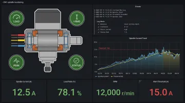
Condition monitoring is the ongoing process of collecting and analyzing data from machine components — vibration, temperature, motor current, acoustic signals — to detect developing faults before they cause failure or quality loss.
That definition matters because it distinguishes condition monitoring from two things shops often confuse it with:
- General machine monitoring (OEE/production tracking): Measures utilization, cycle times, and part counts. Useful for production management, but it won't tell you a spindle bearing is degrading.
- Preventive maintenance: Replaces or services components on a fixed schedule, regardless of actual condition.
Why CNC Machines Are a Good Fit
CNC spindles, ball screws, linear guides, and servo drives are precision components whose degradation follows detectable patterns. Bearing wear, for example, progresses through identifiable stages — from subtle changes in high-frequency vibration signatures, through characteristic defect frequencies, to audible noise and imminent failure. Each stage is measurable, and each carries a different level of urgency.
The goal of condition monitoring is to catch faults in those early stages, when a planned repair can be scheduled on your terms rather than the machine's.
The result is a shift from reactive repairs and fixed service intervals to data-driven interventions timed to actual machine condition — reducing both unplanned downtime and unnecessary maintenance spend.
Key CNC Components That Require Condition Monitoring
Spindle Bearings
The spindle is the highest-value mechanical component on a machining center, and spindle bearing failure is the most expensive preventable failure mode in most shops.
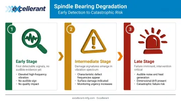
Bearing degradation doesn't happen all at once. It moves through stages:
- Early stage: Elevated high-frequency vibration, often detectable only with sensitive sensors — no audible sign, no quality impact yet
- Intermediate stage: Characteristic defect frequencies appear in the vibration spectrum, indicating surface damage on bearing races or rolling elements
- Late stage: Audible noise, heat generation, dimensional drift — the machine is now at risk of catastrophic failure or scrap production
Simple 40-taper VMC spindle rebuilds run $2,000 to $3,500; high-speed or motorized spindles reach $4,000 to $7,000; horizontal and boring mill spindles go $7,500 to $12,000, per In-House CNC's rebuild cost data. Standard rebuild lead times run 5 to 14 business days — and if the spindle fails during a critical run, that's also 5 to 14 days of lost production.
Ball Screws and Linear Guides
Ball screw and linear guide wear don't announce themselves with noise or heat. They show up in your inspection reports.
As wear introduces backlash and stick-slip behavior, axis motion becomes less precise. Renishaw's thermal growth research illustrates the scale: 50 machined parts can introduce roughly 120 micrometers of linear error in a ball screw, with residual error of ~80 micrometers remaining after 15 minutes of cooling. That's enough to push tight-tolerance parts out of spec without triggering a machine alarm.
Axis motion monitoring, then, is as much about protecting part quality as it is about protecting equipment.
Cutting Tools
Tool wear is detectable through spindle motor current trending. A gradual rise in current at constant feed and speed indicates progressive wear; a sudden spike indicates breakage. Cycle time drift is another signal — a worn tool takes longer to remove the same material.
A 2024 research study using spindle current monitoring and machine learning reported 96.93% accuracy in detecting tool wear condition in CNC turning. That level of detection confidence means fewer surprises mid-run.
Undetected tool breakage is particularly damaging. Scrapped parts are the immediate consequence, but a broken drill or tap lodged in a workpiece can damage the spindle as well — converting a $50 tooling event into a $5,000+ repair.
Servo Drive Systems and Auxiliary Systems
Servo motor and drive bearing wear produces irregular vibration signatures that affect axis positioning accuracy. Monitoring drives complements spindle and axis monitoring for a complete machine health picture.
Two often-overlooked but easy-to-monitor parameters:
- Coolant temperature and flow — directly affect spindle bearing life and thermal stability
- Lubrication condition — degraded lubrication accelerates bearing and guide wear
Types of Condition Monitoring Techniques for CNC Machines
No single technique covers every failure mode. Shops typically combine methods based on which components they're monitoring and their available budget.
Vibration Analysis
Vibration analysis (accelerometers mounted on the spindle housing or machine structure) is the primary technique for detecting bearing faults, imbalance, and misalignment.
Frequency spectrum analysis identifies characteristic defect frequencies that reveal the specific fault type:
- BPFO (ball pass frequency outer race) — outer race damage
- BPFI (ball pass frequency inner race) — inner race damage
- BSF (ball spin frequency) — rolling element damage
The value of spectral analysis is specificity. You're not just getting an alert that something is wrong — you're getting information about what is wrong and roughly how far along the damage has progressed.
Acoustic Emission (AE) Monitoring
AE sensors detect high-frequency elastic waves generated by micro-events like tool edge friction, micro-fractures, and bearing surface contact. For machining applications, relevant AE frequency content typically falls between 67 kHz and 471 kHz, based on tool-wear-related experimental data.
AE is particularly effective for:
- Early-stage bearing faults that fall below standard vibration detection thresholds
- Small tool breakage detection (drills, taps) where current-based detection may be less sensitive
- In-process monitoring where stopping the machine for measurement isn't practical
Current Signature Analysis (Sensorless Monitoring)
Current monitoring uses internal drive signals — no external sensors required — to detect tool wear and drive anomalies. A 2024 study found that a spindle load current ratio above 1.4× the initial value indicates severe tool wear. A separate 2025 study on high-speed engraving detected breakage-related energy spikes in 18 of 20 experiments using current-based sensing.
For shops that want condition data without adding hardware, current monitoring is the logical starting point.
Thermal and Controller-Based Monitoring
These two low-barrier methods work best together:
- Thermal sensors are inexpensive and complement vibration data. A bearing generating both heat and elevated vibration is further along in its degradation than one showing vibration alone — the combination sharpens response urgency.
- Controller-based data requires no additional hardware on protocol-enabled machines. Standards like MTConnect (Version 2.5, released February 2025), OPC-UA, and manufacturer-specific interfaces such as Fanuc FOCAS expose spindle load, axis current, alarms, part counts, and program state directly from the controller.
Platforms like Excellerant support MTConnect, OPC-UA, Fanuc FOCAS, HAAS MNET, and Mazak Mazatrol, and extend connectivity to legacy equipment via serial communications or PLC intermediary devices. A shop running a mix of new and 30-year-old CNCs can pull condition-relevant controller data from the entire fleet into one platform, without replacing controllers.
How to Implement a Condition Monitoring Program
Treat implementation as a phased process. Start with the highest-risk machines and highest-value failure modes, then expand as the program proves its value.
Step 1: Prioritize Machines and Failure Modes
Rank machines by:
- Replacement or rebuild cost
- Spindle hours and utilization rate
- Criticality to current job schedule
- History of unexpected failures
Typical priority order:
- Spindle bearing monitoring on highest-utilization machining centers
- Axis motion monitoring where dimensional rejects have occurred
- Tool life monitoring on high-volume or tight-tolerance work
Step 2: Match Techniques to Failure Modes
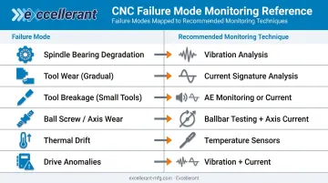
| Failure Mode | Recommended Technique |
|---|---|
| Spindle bearing degradation | Vibration analysis |
| Tool wear (gradual) | Current signature analysis |
| Tool breakage (small tools) | AE monitoring or current |
| Ball screw / axis wear | Ballbar testing + axis current |
| Thermal drift | Temperature sensors |
| Drive anomalies | Vibration + current |
Not every technique is needed on every machine. A targeted approach avoids spending on sensors and infrastructure you don't need.
Step 3: Establish Baselines Before Setting Alerts
Alert thresholds set against absolute values (without a machine-specific baseline) generate false alarms and erode trust in the system. Record healthy-state readings for each monitored parameter first, then set thresholds as percentage deviations from that baseline.
Machine connectivity is a prerequisite for this step. Machines need to transmit data to a monitoring platform in real time. For shops with legacy or mixed-brand fleets, universal connectivity solutions make this practical without controller changes — Excellerant's platform, for example, supports any machine brand and protocol with no additional per-user licensing, including RS-232 serial connections for older equipment.
Step 4: Define Response Workflows
An alert is only as useful as the workflow that follows it. Before going live, define:
- Who receives each alert type
- What inspection or check is triggered
- Go/no-go criteria for continuing to run the machine
- Escalation path if the first responder can't resolve it
ISO severity zones (from ISO 13373 and ISO 17359) provide a structured framework for categorizing alert severity and standardizing response decisions.
Condition Monitoring vs. Preventive Maintenance
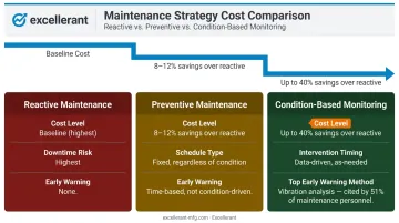
Traditional preventive maintenance (PM) operates on fixed intervals — replace bearings every X hours, lubricate every Y days — regardless of actual component condition. The problem is structural: if a component degrades faster than the interval assumes, it fails before the next scheduled service. If it degrades slower, you're replacing parts that still had useful life.
Condition monitoring shifts the decision trigger from the calendar to the data — you intervene when measurements indicate it's necessary, not because a fixed schedule says it's time.
According to a Reliable Plant predictive maintenance survey, condition-based and predictive maintenance approaches save 8% to 12% over preventive maintenance and up to 40% over reactive maintenance. The same survey found 51% of maintenance personnel identified vibration analysis as the most effective early-warning technology for machine failure.
These two approaches aren't mutually exclusive. PM still covers tasks without detectable precursors — lubrication schedules, filter replacements, coolant changes. Condition monitoring addresses the failure modes that do generate early warning signals.
Predictive maintenance takes this one step further: using trend data and models to forecast when a component will reach a failure threshold. That enables planned intervention at the optimal time — not too early (wasting component life), not too late (unplanned failure). The prerequisite is a history of condition data, which is why condition monitoring comes first.
The Business Case for CNC Condition Monitoring
Aberdeen research cited by Cutting Tool Engineering puts unplanned downtime costs as high as $260,000 per hour across manufacturing broadly — and notes that equipment failure causes 42% of unplanned downtime. McKinsey data shows analytics-based predictive maintenance can reduce machine downtime by up to 50% and maintenance costs by 10% to 40%.
A practical ROI model for a mid-size job shop might look like this:
- Estimate current unplanned downtime: 2 events/month × 4 hours each = 8 hours
- Apply your machine hourly rate (including labor, overhead, and opportunity cost)
- Apply a 30–50% downtime reduction from condition monitoring alerts
- Add avoided spindle rebuilds ($3,000–$7,000 each, plus lost production during rebuild)
- Add scrap reduction from earlier tool wear detection
The cost structure of a condition monitoring program has three components:
- Sensor hardware (vibration sensors, thermal sensors, current transducers): IIoT commodity pricing has driven costs down considerably from where they were five years ago
- Connectivity and software subscription: look for platforms with unlimited user access and no per-seat licensing — this matters as shops add operators and supervisors to the monitoring workflow
- Installation and ongoing review labor: initial setup runs a few hours per machine; after that, the workflow is alert-driven
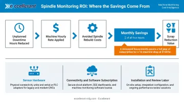
For a shop running 10 machines at $150/hour, recovering even four hours of unplanned downtime per month covers a full year of software subscription costs. The math works at smaller scale than most shops expect.
Frequently Asked Questions
What is the ISO standard for condition monitoring?
Two standards apply: ISO 17359:2018 provides general guidelines for setting up condition monitoring programs using vibration, temperature, tribology, and flow parameters. ISO 13373 is the vibration-specific series covering general procedures, data analysis, and diagnostics across three parts. Neither is CNC-specific, but both give shops a structured framework for formalizing a program.
What are the different types of condition monitoring?
The main types are vibration analysis, acoustic emission monitoring, thermal/infrared monitoring, current signature analysis, and oil/lubrication analysis. For CNC machines specifically, vibration analysis and current-based monitoring are the most widely used, with AE monitoring adding value for small-tool breakage detection and early-stage bearing faults.
What is the difference between condition monitoring and predictive maintenance?
Condition monitoring detects developing faults in real time using sensor data and alerts. Predictive maintenance goes further, using historical trends and models to forecast when a fault will reach a critical threshold — but it depends on condition monitoring data, and you need 6–12 months of history before forecasting becomes reliable.
Can condition monitoring be applied to older or legacy CNC machines?
Yes. Legacy machines can be monitored using external sensors (vibration transducers, thermal sensors, current clamps) that require no controller modification. Connectivity solutions exist to bring even older RS-232-equipped machines onto a monitoring network through serial adapters or PLC intermediary devices, without touching the controller.
How do I know which CNC components to prioritize for condition monitoring first?
Start with the spindle bearing — the the highest-cost failure mode and generates reliable early warning signals through vibration analysis. Follow with ball screw and linear guide monitoring if dimensional rejects are a quality concern, then tool life monitoring for high-volume or tight-tolerance work.
How often should condition monitoring data be reviewed?
Modern platforms provide continuous automated monitoring with alert-based notifications, so daily manual review isn't necessary. Maintenance teams should respond to alerts as they fire and review trend dashboards weekly, with closer attention for machines running critical jobs or showing upward trends in condition metrics.