Industrial Ethernet grew 12% in 2024, according to HMS Networks' annual market survey. That means more PLCs are landing on shop floor networks every year, and more technicians need to know how to connect them properly.
This guide covers the full process — hardware prerequisites, IP configuration, step-by-step setup, post-connection validation, and troubleshooting — applicable to most modern PLCs regardless of brand.
Key Takeaways
- Confirm your PLC has a built-in Ethernet port or a compatible communication module before attempting any network connection
- Assign a static IP address — never DHCP — on the same subnet as the programming PC
- Choose the correct protocol (EtherNet/IP, PROFINET, Modbus TCP) based on your PLC brand and connected devices
- Validate with a ping test and live tag monitoring before returning the machine to production
- In mixed-protocol or legacy environments, document your existing network topology first — unplanned changes here cause the most integration failures
Connecting a PLC to a Network
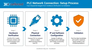
The process moves through four stages: hardware verification, physical connection, IP/software configuration, and validation. Skipping or rushing any stage typically results in intermittent faults or security gaps that are difficult to diagnose later.
A straightforward Ethernet connection on a modern PLC can take under an hour for a competent technician. A legacy or multi-protocol setup may require IT coordination and significantly more time.
Prerequisites and Safety Considerations
Before touching a cable, confirm the following:
- Hardware compatibility: Verify the PLC has a built-in Ethernet port, or that the correct communication module is installed and firmware-compatible (for example, a Rockwell 1756-EN2T for ControlLogix or a Siemens CP 343-1 for S7-300). Before purchasing add-on modules, check Rockwell's ControlLogix Ethernet modules firmware compatibility matrix
- Network infrastructure: Confirm an industrial managed Ethernet switch with available ports and a defined IP range on the target subnet. Clarify whether the OT network is isolated or shares infrastructure with corporate IT
- Software: The PLC programming IDE (Studio 5000, TIA Portal, GX Works, CX-Programmer) is installed, and the correct communication driver or protocol stack is available and licensed
- IT coordination: Get a reserved static IP assignment, understand VLAN segmentation rules, and confirm whether any firewall rules need to be opened for industrial communication ports
Non-negotiable safety condition: Bring the machine to a safe, de-energized, or known safe operating state before making any changes to PLC communication settings. A configuration error mid-run can cause unexpected machine behavior.
Tools and Components Required
Physical materials:
- CAT5e or CAT6 Ethernet cable (straight-through for switch connection; most modern industrial switches include auto-MDI/MDIX)
- Industrial managed Ethernet switch — preferred over unmanaged for VLAN support, port mirroring, traffic prioritization, and fault isolation
- For legacy PLCs lacking Ethernet: a protocol gateway appropriate to the PLC's native port (RS-232, RS-485, or proprietary connector)
Software and access:
- PLC programming IDE for the controller brand
- Communication driver: FactoryTalk Linx for Allen-Bradley; TIA Portal for Siemens
- Network utility for connectivity checks (ping tool or IP scanner)
Optional but useful: Wireshark for advanced protocol-level troubleshooting — not required for standard setups.
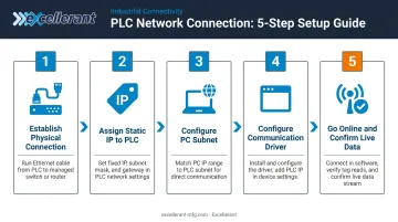
How to Connect a PLC to a Network (Step-by-Step)
Follow a hardware-first, software-second sequence. Attempting to configure IP settings before confirming a physical link is one of the most common sources of wasted troubleshooting time.
Step 1 — Establish physical connection
Plug the Ethernet cable from the PLC's Ethernet port (or communication module port) into the industrial managed switch. Confirm that link status LEDs on both the PLC port and the switch port illuminate. No LED, no link — resolve the physical layer before proceeding.
Step 2 — Assign a static IP address to the PLC
Using the PLC's programming software or front-panel configuration (varies by brand), set a static IP address within the facility's reserved OT address range. Configure the correct subnet mask and default gateway if the PLC needs to communicate outside the local subnet.
Avoid DHCP for PLCs. Rockwell's EtherNet/IP documentation describes commissioning devices with BOOTP/DHCP tools initially, then locking them to static addressing. Omron's documentation notes that IP address protection prohibits FINS/UDP access from nodes with dynamically changed addresses. Address changes break communication.
Step 3 — Configure the same subnet on the engineering PC
Set the PC's Ethernet adapter to a static IP on the same subnet as the PLC. If the PLC is 192.168.1.10, the PC should be 192.168.1.X with the same subnet mask. Run a ping from the PC to the PLC IP before proceeding to software configuration — if ping fails here, a software-level fix won't help.
Step 4 — Configure the communication driver and establish a software path
Open the communication software, create a driver for the correct protocol, enter the PLC's IP address, and verify the controller appears in the browse/discovery window:
- Allen-Bradley: Configure an EtherNet/IP driver in FactoryTalk Linx (embedded in Studio 5000)
- Siemens: Use TIA Portal's network view to add the PROFINET IO device
- Modbus TCP: Use the vendor's driver or a third-party tool such as Modbus Poll for testing
For shops running a mix of PLCs and machine tools across different protocols, configuring each device individually gets time-consuming fast. Excellerant's machine connectivity platform supports MTConnect, OPC-UA, Fanuc FOCAS, HAAS MNET, and Mazak Mazatrol, acting as a protocol gateway that normalizes data from multiple machine types into a single unified platform, without requiring reprogramming of the individual controllers. This is especially useful when onboarding several machines at once.
Step 5 — Go online and confirm program-level communication
Use the "Go Online" function in the PLC programming IDE to establish a live connection to the controller. Confirm that program tags, I/O status, and controller diagnostics are visible and updating in real time. A connection isn't complete until live data is moving.
Post-Connection Checks and Validation
Don't skip this phase. Connections that appear functional but bypass these checks frequently fail during production.
Physical and IP Validation
- Run a sustained ping from the engineering PC to the PLC's IP address — consistent round-trip times with no packet loss confirm a clean physical and IP-layer connection
- Intermittent or failed pings indicate a physical or IP configuration issue to resolve before any software-level validation
Software Validation
- Confirm the PLC appears correctly in the communication driver's device browser
- Verify the controller's status (run/fault/idle) is readable from the programming software
- Confirm live tag values are updating at the expected scan rate — flat values despite an active connection typically indicate a protocol configuration mismatch
IP Conflict Check
Run a network scanner to verify no other device on the subnet shares the PLC's IP address. An IP conflict causes intermittent disconnections that are difficult to trace without this step. Catching it during commissioning is far less costly than diagnosing it during a production stoppage.
Common PLC Network Connection Problems and Fixes
Most connection problems fall into a predictable set of causes. Work through them in order — physical layer first, then IP, then software/protocol — and you'll resolve the majority faster than jumping between layers at random.
PLC Not Appearing in Network Discovery
The PLC doesn't show up in the communication driver's browse window despite an active link LED.
The most common cause is a subnet mismatch — the PC's Ethernet adapter is on a different subnet than the PLC (for example, PC on 192.168.0.x, PLC on 192.168.1.x). Broadcast discovery packets can't cross subnet boundaries.
Fix: Confirm both the PC adapter IP and the PLC's configured IP share the same subnet. Use ping to test reachability, then reconfigure the PC adapter or PLC IP as needed and re-run discovery.
Intermittent Disconnections or Communication Timeouts
The connection establishes but drops periodically, or the programming software reports timeouts mid-session.
Three hardware factors cause the vast majority of these issues:
- Unmanaged consumer switch — replace with an industrial managed Ethernet switch
- Damaged or low-quality cable — test with a known-good cable before chasing software settings
- Duplex/speed mismatch — verify auto-negotiation is consistent on both the PLC port and switch port; either both on auto-negotiate, or both manually set to the same speed/duplex
Firewall or IT Security Blocking Communication
The PLC is reachable by ping, but the programming software can't establish a protocol-level connection — returning a timeout or "host unreachable" error.
A Windows firewall, corporate network firewall, or managed switch ACL is likely blocking the required industrial communication ports. Open only what's needed for your protocol:
| Protocol | Ports to Open |
|---|---|
| EtherNet/IP | TCP/UDP 44818 |
| Modbus TCP | TCP 502 |
| PROFINET | UDP 34964, UDP 49152 |
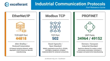
Port assignments confirmed by ODVA, IANA, and Siemens/HMS documentation respectively.
Fix: Work with your IT or network administrator to add specific inbound/outbound rules for the required ports. Don't disable the firewall entirely — open only what's needed.
Pro Tips for a Reliable PLC Network Connection
Maintain a static IP address log. Document every IP address assigned on the OT network and keep it current. When a new device picks up an address already in use, the resulting intermittent conflict is far harder to trace than it needs to be.
Segment OT from IT. Claroty's 2025 OT exposures report analyzed nearly 1 million OT devices across 270 organizations and found 7% exposed with known exploited vulnerabilities tied to ransomware. Use a managed switch with VLANs, or a dedicated router, to isolate PLC traffic from office traffic. For remote access, require VPN authentication — not direct port forwarding through the main firewall.
Excellerant's machine connectivity platform is built with this OT/IT boundary in mind, supporting on-premise deployment and CMMC/NIST 800-171 compliance for defense and quality-regulated shops.
Document before and after commissioning. Record the PLC IP address, subnet, gateway, firmware version, communication module type, and protocol settings. This documentation is what saves you at 2am during a production fault when the original engineer is unavailable.
Know when to bring in a specialist. Some environments genuinely exceed in-house troubleshooting capacity. If the shop floor has legacy PLCs with serial-only interfaces, mixed brands running incompatible protocols, or requirements to push machine data into ERP or MES systems, the integration complexity warrants specialist support. Excellerant brings 30 years of machine tool networking experience to exactly this kind of mixed-protocol, mixed-age environment.
Conclusion
The quality of the initial network setup directly determines long-term reliability. A correctly configured static IP, proper protocol settings, and validated data flow prevent the majority of network-related production disruptions before they happen.
Getting there requires discipline at each stage: document every step, coordinate with IT before connecting OT devices to shared infrastructure, and complete full validation before returning any machine to production service. An hour of proper commissioning consistently costs less than diagnosing an IP conflict mid-shift.
Frequently Asked Questions
What cable do I need to connect a PLC to a network?
A CAT5e or CAT6 Ethernet cable works for most modern PLCs connecting to a switch. Most modern PLC Ethernet ports support auto-MDI/MDIX, so straight-through cables work in nearly all cases. Legacy PLCs with only serial ports require a protocol converter or gateway rather than a standard Ethernet cable.
How do I assign an IP address to a PLC?
IP assignment is done through the PLC programming software (TIA Portal for Siemens, Studio 5000 for Allen-Bradley) or via a front-panel interface on some models. Always use a static IP rather than DHCP, and coordinate with your network administrator to reserve an address within the OT subnet range.
Can I connect older legacy PLCs to a modern Ethernet network?
Most legacy PLCs with serial (RS-232/RS-485) or proprietary ports can be connected via a protocol gateway that translates the PLC's native communication to Ethernet-based formats like Modbus TCP. Devices like the Moxa MGate MB3180 or HMS Anybus Communicator handle this translation without replacing the controller.
What industrial protocols does a networked PLC use?
The most common options are EtherNet/IP (Allen-Bradley/Rockwell systems), PROFINET (Siemens), Modbus TCP (brand-agnostic, widely supported), and EtherCAT (high-speed motion applications). The correct protocol depends on the PLC brand and what other devices or systems the PLC needs to communicate with.
How do I secure a PLC after connecting it to a network?
Use static IPs and disable unused communication ports on the PLC. Segment the OT network from IT using VLANs or a dedicated firewall. Require VPN authentication for any remote access rather than direct port forwarding. Never expose a PLC directly to the public internet.
Do I need to separate the PLC network from the corporate IT network?
Yes. OT and IT networks have different uptime, security, and traffic requirements that make separation essential. At minimum, use a managed switch with VLANs to isolate PLC traffic. Higher-security environments should add a dedicated industrial firewall or DMZ, per NIST SP 800-82r3 guidance.